 キャップバランサーが
ヒンジを変えるだけで
こんなに軽く
なっていいのか!
ヒンジを
変えるだけで
こんなに軽く
なっていいのか!
が
重い蓋やカバーの開閉をアシスト
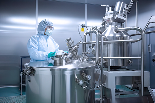
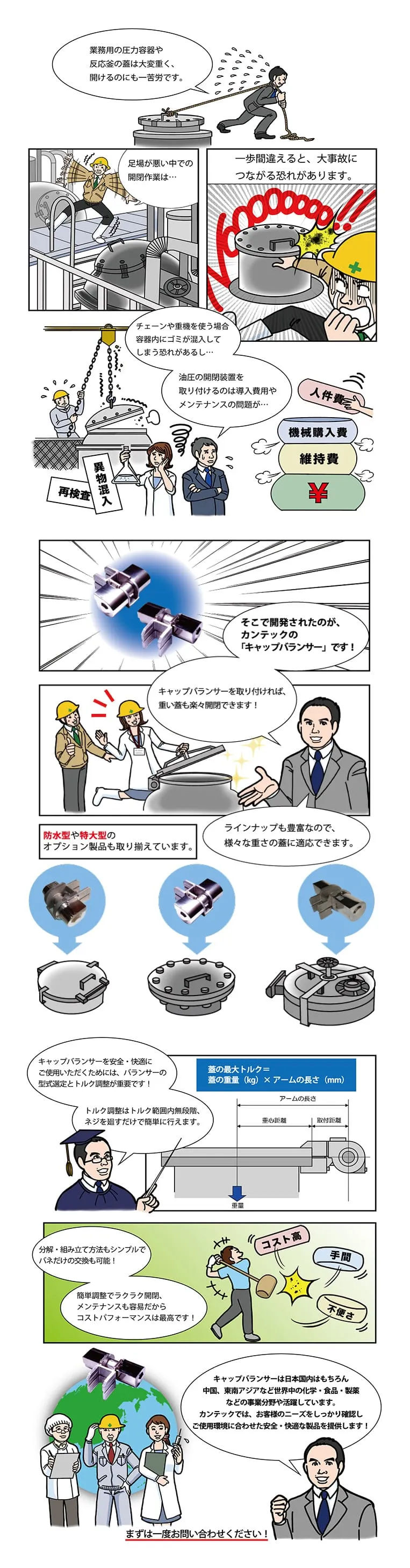
圧力容器や反応釜の蓋は大きくて、大変重く、指を挟むなどの怪我のリスクがあります。
「仕方ない」と諦めずに、キャップバランサーの導入を検討してください。


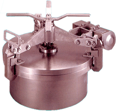
反応釜、攪拌槽、マンホールなどの 「重い蓋」「危険な開閉」から解放されます
反応釜、攪拌槽、マンホールなどの 「重い蓋」「危険な開閉」から 解放されます
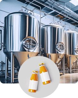
食品製造設備

化粧品製造設備
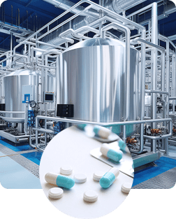
医薬品製造設備
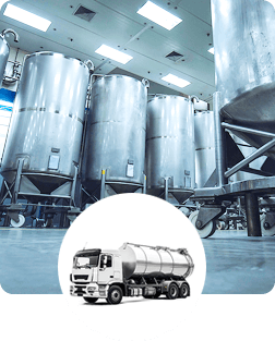
重化学工業設備
工場設備のマンホール、ハンドホールの重い蓋から各種装置のカバーまで、幅広い産業の設備に取付けが可能です。
 こんなにラクラク!
驚くほど軽くなります

こんなに軽くなる!重い蓋の救世主
既設設備にも、新設設備にも取付可能
医薬品製造、化粧品製造、食品製造などさまざまな業種の幅広い設備に、幅広い製品ラインナップで対応しております。既設、新設どちらの設備にも取付可能です。

製品のご案内
PRODUCTS防水タイプ、特大サイズもありますので、お気軽にお問い合わせください。
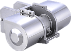
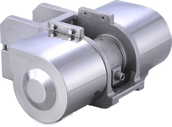
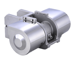
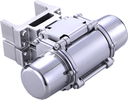
キャップバランサー
ワンタッチ開閉装置
お知らせ
NEWS重大な事故になる前に キャップバランサーで対策を!
よくあるご質問
FAQQ 現在稼働中の設備のマンホールに取り付けることはできますか?
条件によりますが、既設マンホールへの取り付けも可能です。その場合、型式の選定、取り付けスペース、取り付け工事の可否などの確認が必要です。
Q どのくらいの力で蓋の開閉ができるようになりますか?
蓋の重さによって異なります。蓋の条件等をお知らせいただければ、おおよその開閉力を計算して、お伝えいたします。
Q アフターサービスはありますか?
適切な条件下で、納入後1年以内に不具合が生じた場合には、部品または製品全体の交換品をご提供いたします。
お問い合わせ・資料請求
お電話でのお問い合わせ
お使いの設備に取付できるか回答しますので、お問い合わせください。
お探しのヒンジをご案内いたしますので、お問い合わせください。
実装可能な製品をご提案いたしますので、ご相談ください。
